Upgrading a Creality CR-X Pro with an E3D Chimera+ Hotend
What follows has been a bit of an odd project to me. My 3D printer so far has been a Flashforge Creator Pro (you can see it in action on my YouTube channel), and it generally “just works.” The thought of modding a 3D printer was as remote to me as messing with the innards of my (paper) laser printer. That changed when my friend Marcus approached me to find a new home for his second printer, the aforementioned CR-X Pro (specifically, an upgraded version sold by TinyMachines3D). The printer has an appealingly large print volume, but the catch was that it no longer had a hotend. However, Marcus had a new dual-nozzle E3D Chimera hotend already at hand, along with a bunch of crimped extension cables. So with a bunch of goodies stashed in my hallway, I set out to solve this electromechanical puzzle. If you’re already familiar with messing with your printer, this post will contain a bunch of obvious facts, quite possibly some solutions contrary to best practices, and maybe a couple of chuckles as I work through the project by trial and error. Lots of error. But if you’re a casual 3D-printing enthusiast, there are hopefully a few useful pieces of information in here, too.
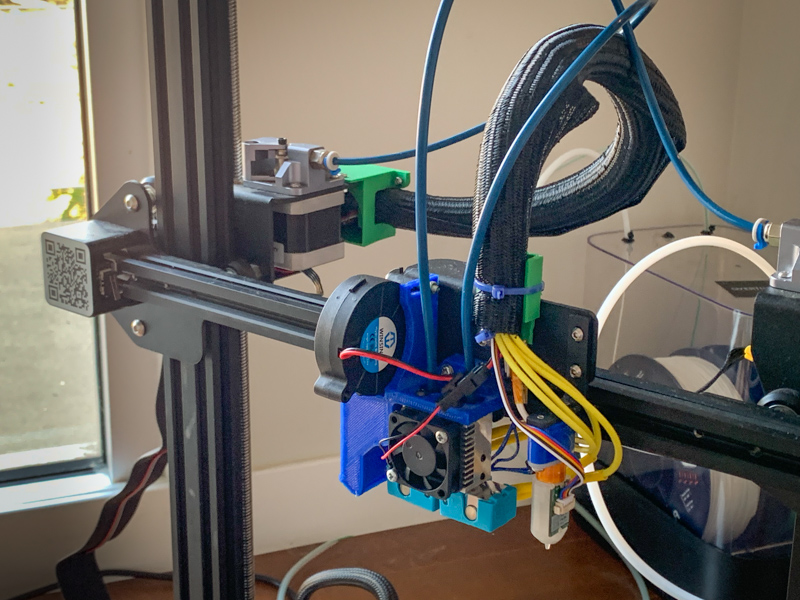
Assembling the Hotend
To get started, the first step is to assemble the hotend. E3D has easy-to-follow instructions on their website. The hotend comes with two 0.4mm nozzles, but Marcus also got a set of nozzles in a bunch of different extra sizes. Since I’ve two .4 nozzles in the Flashforge, I thought it’d be fun to have some more variety and go with a very small one (the smallest one I have is .25) and a very large one (such as the .8 one in the set). After some searching I came across a great article on the Prusa Blog that discusses pros and cons of various nozzle size. In a nutshell, for very small nozzles, clogging is an issue. Large nozzles result in parts with overly coarse looks at only moderate gains in printing speed. And I came across some remarks that beefier heating elements may be necessary to melt enough plastic at higher printing speeds.
Eventually, I settled on a .35 nozzle (just slightly smaller than the default .4) and a .6 one, which is the “alternative” size the post on the Prusa Blog recommends as a good trade-off between speed and accuracy. That will give me some options for prints without having to worry about nozzle swaps. And even without taking advantage of the dual-nozzle design, it is great to have both sizes ready to go for single-nozzle prints. (For what it’s worth, my Flashforge has also a dual extruder/dual nozzle design, and I’ve rarely printed with both.)
The hotend can be assembled up to the hot-tightening step. To heat it up, we first need to get everything wired up. Also, the firmware of the printer needs to be updated to accommodate for the new hardware.
Mounting the Hotend
To get the Chimera onto the CR-X’s carriage, some sort of adapter is needed. While the Chimera has its own cooling fan, we also need a layer fan to cool the printed plastic. The stock one won’t work since it doesn’t fit the Chimera at all. Luckily, I found a Chimera mount for a Creality Ender 4 made by Thingiverse user krestoverson.
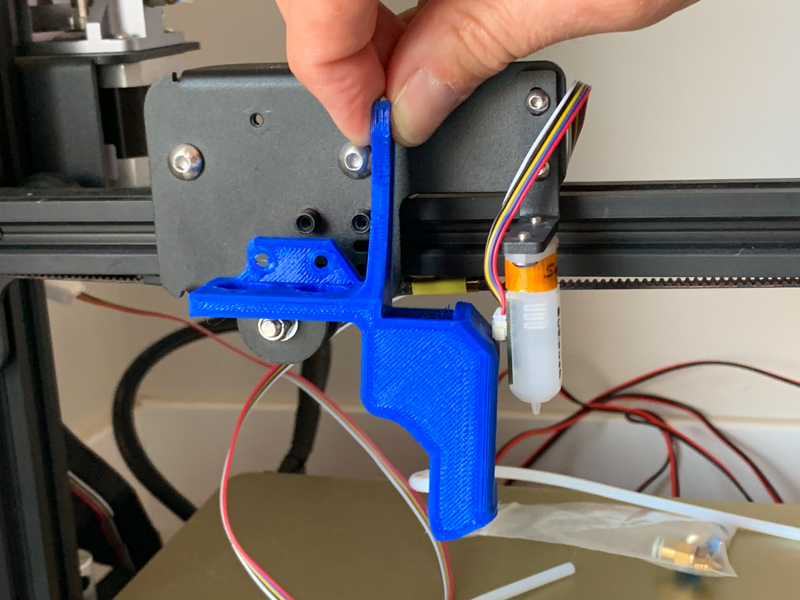
I’ve printed the part on the Flashforge to try it out. Almost there… the BLTouch gets in the way of the air duct. So either the BLTouch needs to be mounted elsewhere, or the duct needs to move. I opted to simply mirror the part to have the duct on the left side of the carriage. However, there is a screw and a nut in the way that interfere with the air duct.
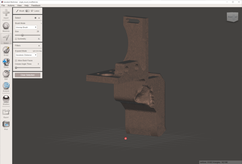
To address that problem, I fired up Meshmixer to make some very non-graceful modifications. First, I extended the flat surface facing the carriage by a few millimeters. Not only does that give more clearance, but it also ensures that the part fits all the way over the screw posts and lays flush against the carriage. Presumably, some tolerances didn’t work out as intended in my print (or the Ender 4 has different mounts than the CR-X). Next, I used the sculpting tools to carve out some space for the screw and nut.
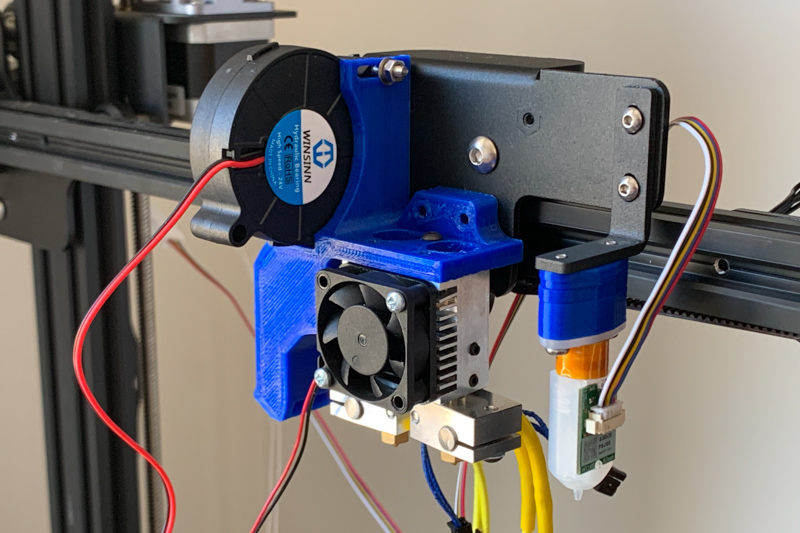
The result is aesthetically questionable, and in hindsight spending some time to sort it out in Fusion 360 would have been a cleaner route. However, the printed modified part fits and is fully functional. I ordered a fan, attached it to the mount, mounted the hotend, and then mounted the assembly onto the carriage of the printer. So far so good…
One final step: the BLTouch needs to be lowered so that its high and low positions are above and below the nozzle height. For that, I found a set of shims on Thingiverse.
Wiring
As part of this project, I’ve learned more about wire connector standards (or lack thereof) than I would have hoped for… Up until now, I’ve only had crimping tools for Dupont connectors in my toolbox since those are handy for breadboard work. The printer uses JST-XA and JST-XH connectors. Some parts use two-pin versions of the Molex Micro-Fit system. (To mix things up, for that connector system there are even a horizontal and a vertical 2-pin version.) Marcus had already replaced some connectors with JST-SH and crimped Molex Mini-Fit connectors on the heater wires (as the name implies, Mini-Fit is a larger version of Micro-Fit).
For JST-XA and JST-XH, the sets I found all have PCB-mounted male connectors while the female ones are plugs. Male plugs for cable-to-cable connection exist (as evidenced by their presence in the printer) but seem to be harder to come by. However, JST-SH allows for easy cable-to-cable connections.
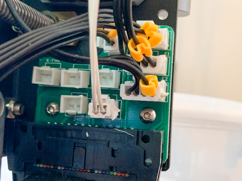
The CR-X has a circuit board with various connectors on its gantry. A ribbon cable coming up from the base connects it to the electronics down below. I’ve connected the fan on the hotend heatsink and the layer fan both to that circuit board (“FAN” and “K-FAN” on the silkscreen). In addition, each nozzle has a thermistor to measure the nozzle temperature and a heating element to bring it up to temperature. The stock hotend only has one of each, so that’s all that is available via the gantry connectors.
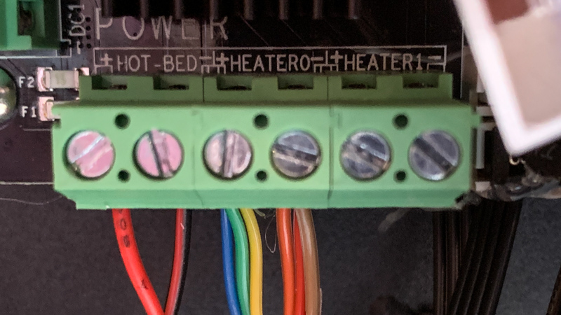
Opening up the bottom of the printer reveals the main circuit board. The board has a terminal block with two connectors for “Heater 0” (each connected to three bundled wires of the ribbon cable) and “Heater 1” (unconnected). Two wires of the ribbon cable feed into a connector labeled “TH1” (i.e. thermistor 1) on the board’s silkscreen. Unintuitively, TH1 goes with Heater 0. A second connector, TH2, is for the thermistor to be used with Heater 1. For TH2, I crimped a long two-wire cable that I can route up to the gantry.
For both heaters, I’m using cables that Marcus had already prepared. I’ve also routed those up to the gantry in parallel to the TH2 cable (and I’ve disconnected the ribbon cable previously used for Heater 0). In the process, I managed to damage one of the Mini-Fit connectors. Instead of replacing it and finding a proper crimping tool, I’ve used Wago 221 splicing connectors. Those are a painless way to splice cables while supporting large currents without much fuss.
Firmware
The printer uses Marlin as its firmware. The friendly team at TinyMachines3D pointed me to the InsantityAutomation fork of Marlin, which is the version this printer is using. It comes with handy configuration settings that set up Marlin for a CR-X Pro without having to mess with the majority of the settings. There even are #define statements for a Chimera hotend in the code (for the prior version with 18mm nozzle pitch; the Chimera+ nozzles are 20mm apart). A handful of settings needed to be updated. Most importantly, Marlin needs to know that there are two nozzles now and the types of thermistors used. I’ve also configured the offsets between the nozzles and the offset between the first nozzle and the BLTouch probe. Compiling and flashing the firmware is straightforward, and with that the next step is hot tightening.
For the first nozzle, heating it using the touch screen was no issue. However, to my surprise no controls for the second nozzle showed up. As it turns out, the printer uses a “DWIN” display. The display has its own MCU and memory, and it displays a premade UI that can be updated over an SD card slot on the display’s PCB. That allows for convenient touch controls, including controls for numeric data input, but it also makes it harder to make changes to the UI. TH3D offers a replacement kit with a regular LCD that is directly controlled by Marlin. For now, I opted to neither replace the display nor to mess with the display firmware, so I heated the second nozzle via USB over the machine control panel of Simplify3D. While controlling the machine remotely this way isn’t an issue, the main drawback is that there’s no temperature readout for the second nozzle on the machine itself.
Getting Ready for the First Print
It’s time to try everything out. For starters, the goal is to print with the primary nozzle, which I wired to be the right one of the Chimera. Small wrinkle: the left extruder is the one that is associated with that nozzle, so I had to do a quick swap of the Bowden tubes.
The next hurdle was the z-offset of the nozzle in relation to the BLTouch. The nozzle just wouldn’t home properly and hover a couple of millimeters over the bed. Trying a couple of different distances in the firmware by setting NOZZLE_TO_PROBE_OFFSET did not get me any closer either.
After some searching, I came across some handy instructions on how to set the z-offset for probes like the BLTouch. Key takeaway: the value can be set using G-code, not just by recompiling the firmware, using the M851 command, and the values can be stored in the printer’s EEPROM. G-code can be entered using Simplify3D’s machine control panel. Also useful: the M503 command to get the current settings.
Simplify3D uses a start script that loads filament (sometimes resulting in a blob of plastic dropping while the nozzle is at an x-coordinate of 5mm, on the left side of the printer) and then wiping the nozzle over the edge of the bed. With the two nozzles of the Chimera, the right nozzle is now always over the bed for low x-values. Updating the start script to move the the right side instead fixes that:
G1 X320 Y10 Z0.2 F3000 ; move to wait position
G92 E0 ; reset extrusion distance
G1 E90 F1500 ; load filament
G92 E0 ; reset extrusion distance
G1 X160 E15 F600 ; prime nozzle
G1 X140 F5000 ; quick wipe
G0 or G1 move to the specified coordinates; G92 sets a coordinate to a specified position, i.e. G92 E0 specifies that the current filament position in the extruder shall now be 0mm.
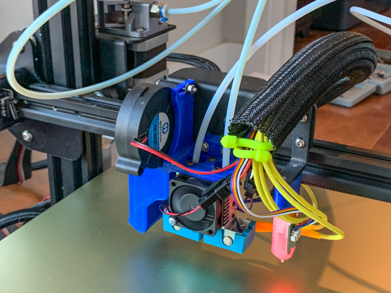
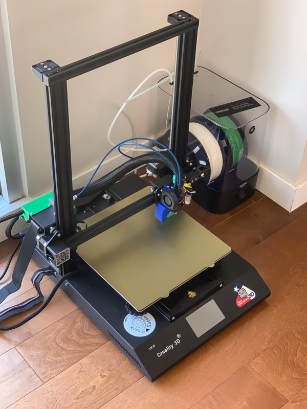
And with some rudimentary cable management, we’re ready to print. The cables are tied together, and I then stuffed them into a cable sleeve. First order of business is to print a cable guide for the hotend that can support the sleeve. Conveniently, there’s an unused tapped bore for an M3 screw on the carriage.
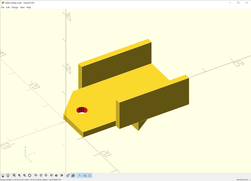
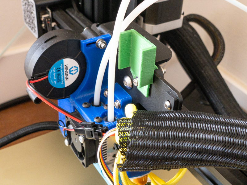
Using OpenSCAD, I’ve designed a quick cable guide that can be screwed into the spare hole. On the back it has a small ledge to prevent it from turning when the cables apply torque. The sleeved cables are zip-tied to the guide to prevent them from dangling into the print area. Progress. (The back part of the sleeve is still dangling on the print bed, but we’ll get there later.)
Putting the Second Nozzle to Use
Next up: printing with the second extruder. Small wrinkle this time: the layer fan doesn’t come on (presumably the firmware or the slicer wants to turn on a second layer fan, which my setup doesn’t have). M106 S255 P0 takes care of that and spins the fan up to full speed.
With that sorted, it’s time to use both nozzles. As a quick test, I’ve configured Simplify3D to use the first extruder as the primary one and the second extruder for infill. What I had expected to be a quick validation turned out to surface two new problems. The first nozzle prints fine, but for the second nozzle extrusion happens several millimeters over the part, resulting in some dreaded air spaghetti. Next, when switching between nozzles, the carriage moves to the very right of the gantry, exceeding the maximum x-value that is mechanically possible. The x-axis stepper motor lodges its complaints with nasty sounds.
M503 to the rescue again. Taking a look at the output, this setting raised an eyebrow:
; Hotend offsets:
M218 T1 X20.00 Y0.00 Z-3.100
The second nozzle (T1), is 20mm to the left of the first nozzle (T0), and it is at the same height. The correct setting is therefore M218 T1 X-20 Y0 Z0. Setting this fixes one of the two problems. Scanning through the settings some more, this command looks suspicious, too:
; Tool-changing:
M217 S80.00 B0.00 E2.00 P276.00 R3000.00 U1500.00 \
  F255 G10 A0 L0.00 W1.00 X315.00 Y10.00 Z2.00
The M217 command is for filament swaps and tool changes. Presumably, this is a relic from when the printer had a single nozzle and a filament Y-splitter connecting it to two extruders. When switching filaments, the nozzle is moved to the very right to purge the existing filament and load the new one.
Wondering what is appropriate for a dual-nozzle design, I connected to my Flashforge to see what it uses. Unfortunately, it doesn’t support plain-text G-code (and I didn’t intend to figure out how to use its binary protocol at the moment). While the x-position of 315mm seems dubious, moving to 320mm was not a problem when addressing the wiping challenges earlier—but I changed some offsets since, so trying a smaller value seems prudent. Hence, I copied the command and changed the X315.00 parameter to X295.00.
Hopeful that that gets me further, I sent the command to the printer. Yet, nothing happened. The printer neither acknowledged the command nor did it react to anything else in the console anymore. Sending M503 also resulted in more silence and not the hoped-for response with the updated settings.
After some experimentation, I noticed that the firmware reacts similarly to other long G-code strings. A wild guess: somewhere in the code, there is a command buffer that overflowed. Getting to the bottom of that is on my to-do list. Just disabling the park feature, which is not needed for the two-nozzle setup, solves the problem: M217 S0 B0 E0 W0 (a significantly shorter command string). And with that, a print with two nozzles also works. If not for…
Filament Jams
During all the previous steps, I’ve had several jams with prints failing or filament not loading. I first assumed a clogged nozzle – maybe some particles that got into the system during assembly. After the dual-nozzle adventure, I ended up being unable to load filament into either nozzle. Both nozzles having the same problem made me suspicious of the particle theory.
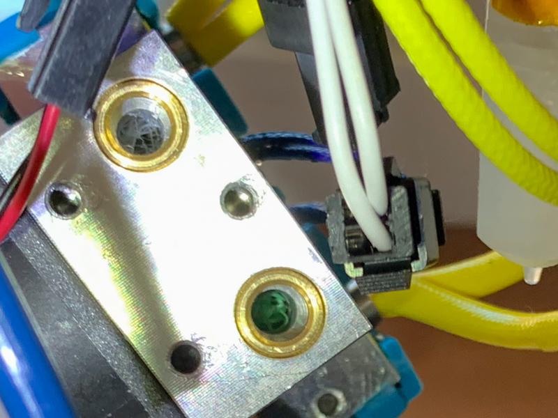
Per suggestion from Robby, I took a look at the top part of the hotend. And on both sides, there’s a nest of stringy filament sitting on top of the heatbreak, What likely happened is that I didn’t insert the Bowden tubes far enough, and stringy filament started accumulating on long retractions, e.g. after a print. Removing the plastic was a significantly easier fix than having to take the whole hotend apart.
Wrapping up Cable Management
There’s one more thing to do: while the cables are nicely attached to the carriage, the back end still dangles on top of the back of the bed. To tackle that, I’ve designed a small box that can be screwed to the gantry in Fusion 360.
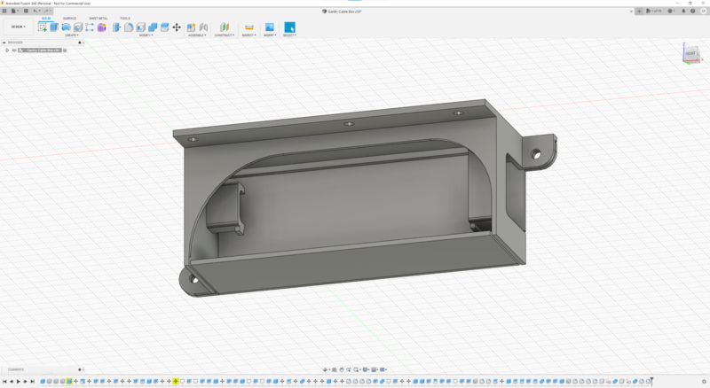
Inside the box, the sleeved cables coming up from the PCB in the base and the sleeved cables coming from the carriage with the hotend are zip-tied in place. The box is then screwed shut using two M3 screws and nuts. I considered using a tap to cut thread into the plastic like I did for the joystick and paddle controller designs. However, this box will be opened more frequently than the controllers, so a solution less susceptible to wear works better. Also, I’ve settled for just two screws for easy access.
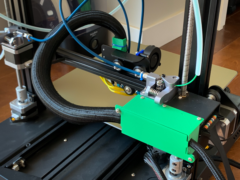
Printing the two parts of the box, mounting it to the gantry, and zip-tying the cable sleeves to it wraps up this little project. You can see the result in the picture above.
Lessons Learned
When I embarked on this project, it sounded significantly harder than it turned out to be. The 3D-printing community is full of people that share their insights, designs, and software, which clears a lot of the obstacles for a project such as this one.
I am not entirely happy with the wiring. Having the heater cables coming out of the back of the hotend means that they get close to the posts of the z-axis. Routing them towards the front would have been cleaner. Also, having the first nozzle on the right, connected to the left extruder, is a bit messy. That can be changed with a bit of extra work, of course.
Next Steps
There are still a bunch of things to do. Replacing the touchscreen controls with an LCD that allows controlling both nozzles, for example. Next, the hotend mount could use some improvements. Aside from a more precise modification than my Meshmixer sculpting, moving the hotend towards the left will improve the available range on the x-axis. Dual fans, one for each nozzle, are another possibility. Lastly, the Bowden tubes and cabling interfere with the cross bar and belt up top, which will pose a problem for prints with a lot of height.
Subscribe via RSS